
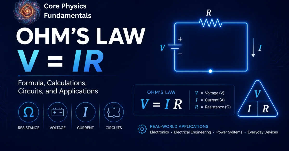
Ohm’s Law (V = IR): Formula, Calculations, Circuits, and Applications
Every electrical circuit you interact with, from the screen you are reading this on to the power grid delivering energy to your home, operates according to a single equation published in 1827: V = IR. This is Ohm’s Law, and it is the foundational relationship that connects voltage, current, and resistance in an electrical circuit.
Whether you are a student solving your first circuit problem, an engineer designing a power supply, or someone who simply wants to understand why a fuse blows, Ohm’s Law provides the framework. This guide walks through the core formula and its rearrangements, the Ohm’s Law triangle, power calculations using the Ohm’s Law wheel, step-by-step worked examples, and real-world applications — covering everything from basic definitions to the microscopic physics behind electrical resistance.
History and Origin of Ohm’s Law
Georg Simon Ohm’s Discovery (1827)
Georg Simon Ohm (1789–1854) was a German physicist and mathematics teacher who conducted meticulous experiments on electrical conduction in the 1820s. His key innovation was using a thermocouple as a stable voltage source (rather than the unreliable voltaic piles of the era) and a torsion galvanometer as a sensitive current detector.
In 1827, Ohm published his findings in a treatise titled Die galvanische Kette, mathematisch bearbeitet (The Galvanic Circuit Investigated Mathematically), in which he demonstrated the proportional relationship between voltage and current for metallic conductors.
His work was initially met with skepticism and even hostility from parts of the German academic establishment. Despite this resistance, the scientific community eventually recognized the importance of his contribution. The Royal Society of London awarded Ohm the Copley Medal in 1841, and in 1881 the international scientific community adopted the “ohm” (Ω) as the official unit of electrical resistance in his honor.
Ohm’s work preceded the discovery of the electron by nearly 70 years (J.J. Thomson identified the electron in 1897). Ohm established the empirical law without any knowledge of the microscopic mechanism responsible for electrical conduction — a testament to the power of careful experimental physics.
What Is Ohm’s Law? (Definition and Core Concept)
Ohm’s Law
The electric current flowing through a conductor is directly proportional to the voltage (potential difference) applied across it, provided the temperature and other physical conditions remain constant. The constant of proportionality is the resistance of the conductor.
In practical terms, Ohm’s Law tells you three things:
- Increasing the voltage across a component pushes more current through it.
- Increasing the resistance of a component reduces the current for the same voltage.
- For any ohmic conductor, the ratio of voltage to current is always the same value — its resistance.
This relationship was first described experimentally by the German physicist Georg Simon Ohm and remains the single most frequently used equation in electrical engineering, electronics, and physics education.
Direct Relationship Between Voltage, Current, and Resistance
The relationship Ohm discovered is linear. If you double the voltage across a fixed resistor, the current through it doubles. If you triple the resistance while keeping the voltage constant, the current drops to one-third of its original value.
This linear proportionality is what makes a conductor “ohmic.” It is worth noting that Ohm’s Law is not a universal law of nature in the same category as the conservation of energy. Rather, it is an empirical observation about the behavior of certain materials under specific conditions. Many components — diodes, transistors, gas discharge tubes — deliberately violate this linearity, and understanding where Ohm’s Law applies (and where it breaks down) is what separates a working knowledge of circuits from a deep one.
The Fundamental Formula: V = I × R
The mathematical statement of Ohm’s Law is:
V = I × ROhm’s LawWhere:
- V = voltage across the conductor, measured in volts (V)
- I = current through the conductor, measured in amperes (A)
- R = resistance of the conductor, measured in ohms (Ω)
This equation is the starting point for nearly every circuit calculation. It can be rearranged to solve for any one of the three quantities when the other two are known, which is the basis of the Ohm’s Law triangle described later in this article.
Understanding the Key Variables: V, I, and R
Before applying the formula, it helps to understand what each variable represents physically — not just what number to plug in.
Voltage (V) — Electrical Potential Difference (Volts)
Voltage, symbolized as V and measured in volts (V), is the electrical potential difference between two points in a circuit. It represents the amount of energy transferred per unit charge. Formally, one volt equals one joule per coulomb:
1 V = 1 J/CDefinition of one voltThink of voltage as the “electrical pressure” that drives charge through a conductor. A 9 V battery provides 9 joules of energy for every coulomb of charge it pushes around the circuit. A standard household outlet in North America supplies approximately 120 V (or 230 V in most of Europe, Asia, and Africa), delivering proportionally more energy per coulomb.
Without a voltage difference, no current flows. A wire connected between two points at the same potential carries zero current, regardless of how low its resistance is.
Current (I) — Flow of Electric Charge (Amperes)
Current, symbolized as I and measured in amperes (A), is the rate at which electric charge flows past a point in a circuit:
I = Q / tCurrent — charge per unit timeWhere Q is the charge in coulombs and t is the time in seconds. One ampere means one coulomb of charge passes a given point every second.
In metallic conductors such as copper wire, current is carried by free electrons. These electrons drift slowly through the lattice — typically a fraction of a millimeter per second — but the electrical signal itself propagates at nearly the speed of light. This distinction matters: when you flip a light switch, the electric field propagates almost instantaneously, even though individual electrons barely move.
By historical convention (dating back to Benjamin Franklin), current direction is defined as the direction positive charge would flow — from the positive terminal to the negative terminal. In metals, the actual charge carriers (electrons) move in the opposite direction. This “conventional current” convention is used universally in circuit diagrams and engineering practice.
Typical current values in everyday devices include approximately 0.02 A for a standard LED, about 0.5 A for a phone charger, roughly 10 A for a household kettle, and around 200 A for an automotive starter motor.
Resistance (R) — Opposition to Electric Current (Ohms)
Resistance, symbolized as R and measured in ohms (Ω), quantifies how much a material opposes the flow of electric charge. Higher resistance means less current for the same applied voltage.
At the atomic level, resistance arises because conduction electrons collide with the vibrating atoms (ions) of the conductor’s crystal lattice. Each collision transfers kinetic energy from the electron to the lattice, which we observe macroscopically as heat. This is the principle behind every resistive heating device, from a toaster to an incandescent light bulb.
The ohm is defined through Ohm’s Law itself: one ohm is the resistance of a conductor through which one ampere of current flows when one volt is applied across it.
1 Ω = 1 V / 1 ADefinition of one ohmCommon orders of magnitude: a short piece of copper wire has a resistance of a few milliohms (mΩ), a standard carbon-film resistor might be 1 kΩ (1,000 Ω), and an insulating material such as dry rubber can have a resistance exceeding 10¹³ Ω.
The Hydraulic Analogy: Visualizing Electricity as Water Flow
One of the most effective ways to build intuition for Ohm’s Law is to compare an electrical circuit to a water system:
- Voltage is analogous to water pressure. Higher pressure pushes more water through a pipe; higher voltage pushes more current through a conductor.
- Current is analogous to flow rate (liters per second). Just as a flow meter measures how much water passes per unit time, an ammeter measures how many coulombs of charge pass per second.
- Resistance is analogous to pipe constriction. A narrow or long pipe restricts water flow; a thin, long, or high-resistivity conductor restricts current.
In this analogy, Ohm’s Law (V = IR) becomes: pressure = flow rate × restriction. If you increase the pressure (voltage) on a pipe with fixed constriction (resistance), the flow rate (current) increases proportionally. If you pinch the pipe tighter (increase resistance), the flow rate drops for the same pressure.
This analogy has limits — electricity and water are fundamentally different phenomena — but it is a reliable starting point for grasping the proportional relationships in Ohm’s Law.
The Ohm’s Law Triangle and Formula Rearrangements
The Ohm’s Law triangle (sometimes called the VIR triangle or Ohm’s Law triangle diagram) is a visual mnemonic that makes formula rearrangement intuitive. It arranges the three variables into a triangle with V at the top and I and R side by side at the bottom.
To use it, cover the variable you want to find. Whatever remains is the formula:
- Cover V → I × R (multiply I and R)
- Cover I → V / R (divide V by R)
- Cover R → V / I (divide V by I)
How to Calculate Current: I = V / R
When you know the voltage across a component and its resistance, current is found by dividing voltage by resistance:
I = V / RCurrent from voltage and resistanceThis is the most frequently used rearrangement in practice. For instance, to determine whether a wire gauge is adequate for a circuit, you first calculate the expected current and then check it against the wire’s rated ampacity.
How to Calculate Resistance: R = V / I
When you know the voltage across a component and the current through it, resistance is found by dividing voltage by current:
R = V / IResistance from voltage and currentThis form is essential for characterizing unknown components. If you measure 5 V across a resistor and 0.025 A through it, its resistance is R = 5 / 0.025 = 200 Ω.
How to Calculate Voltage: V = I × R
When you know the current through a component and its resistance, voltage is found by multiplying current and resistance:
V = I × RVoltage from current and resistanceThis form is commonly used when analyzing voltage drops across individual components in a series circuit. Each resistor “consumes” a portion of the total supply voltage equal to I × R, and the sum of all individual voltage drops equals the total supply voltage (a consequence of Kirchhoff’s Voltage Law).
Calculating Electrical Power (P) Using Ohm’s Law
Ohm’s Law becomes even more powerful when combined with the equation for electrical power. Power is the rate at which electrical energy is converted into other forms (heat, light, mechanical motion) and is measured in watts (W).
The Power Formula: P = V × I
The fundamental power equation states:
P = V × IElectrical powerPower in watts equals the voltage in volts multiplied by the current in amperes. A 230 V kettle drawing 10 A, for example, consumes 2,300 W (2.3 kW) of electrical power.
Combining Power and Resistance: P = I²R and P = V²/R
By substituting Ohm’s Law into the power formula, two additional expressions emerge:
Substituting V = IR into P = VI:
P = I²RPower from current and resistanceThis form reveals that power dissipated in a resistor scales with the square of the current. Doubling the current through a resistor quadruples the heat it generates — a critical insight for fuse selection and wire sizing.
Substituting I = V/R into P = VI:
P = V² / RPower from voltage and resistanceThis form is useful when you know the voltage across a component and its resistance but not the current. It is frequently applied in calculating power dissipation in heating elements and in transmission line loss analysis.
The Ohm’s Law Power Wheel Explained
The Ohm’s Law power wheel (also called the Ohm’s Law circle or Ohm’s Law chart) is an expanded reference tool that organizes all twelve possible formulas relating V, I, R, and P into a single circular diagram. The wheel is divided into four quadrants, one for each variable:
Ohm’s Law Power Wheel — All 12 Formulas
To find Voltage (V): V = I × R | V = P / I | V = √(P × R)
To find Current (I): I = V / R | I = P / V | I = √(P / R)
To find Resistance (R): R = V / I | R = P / I² | R = V² / P
To find Power (P): P = V × I | P = I² × R | P = V² / R
The wheel eliminates the need to memorize individual formulas. Locate the variable you need in the outer ring, then choose the formula from that quadrant that matches the two values you already have. Electricians, technicians, and students routinely use this chart as a quick reference during practical work.
Step-by-Step Worked Examples (With Solutions)
Example 1: Calculating Current in a Simple LED Circuit
Problem: A standard red LED requires a forward voltage of 2 V and a maximum continuous current of 20 mA (0.020 A). You want to power it from a 9 V battery. What value of series resistor do you need?
Solution:
Step 1: Determine the voltage that must be dropped across the resistor.
V_R = V_Supply − V_LED = 9 − 2 = 7 V
Step 2: Apply Ohm’s Law to find the resistance.
R = V_R / I = 7 / 0.020 = 350 Ω
Step 3: Select the nearest standard resistor value. The closest standard value is 330 Ω (which gives 21.2 mA — acceptably close) or 390 Ω (which gives 17.9 mA — slightly dimmer but more conservative). A 390 Ω resistor is the safer choice for LED longevity.
Example 2: Finding Resistance for a Household Appliance
Problem: A 1,500 W electric space heater operates on a 120 V supply. What is its operating resistance, and how much current does it draw?
Solution:
Step 1: Find the current using P = VI.
I = P / V = 1500 / 120 = 12.5 ACurrent draw of the heaterStep 2: Find the resistance using Ohm’s Law.
R = V / I = 120 / 12.5 = 9.6 ΩOperating resistanceThis low resistance is typical for heating elements. Notice that this current draw is close to the 15 A rating of a standard residential circuit breaker in North America, which is why high-wattage heaters should be on a dedicated circuit.
Example 3: Finding Required Voltage for a Load
Problem: An automotive relay coil has a resistance of 80 Ω and requires 150 mA (0.15 A) to activate reliably. What minimum voltage must be applied?
Solution:
V = I × R = 0.15 × 80 = 12 VMinimum activation voltageA standard 12 V automotive battery meets this requirement precisely, which is why 12 V relay coils are the standard in automotive electrical systems.
Example 4: Calculating Power Dissipation and Heat Loss
Problem: A 10 Ω resistor carries 3 A of current in a circuit. How much power does it dissipate as heat? If this resistor is rated for 5 W, is it safe to use?
Solution:
P = I²R = 3² × 10 = 9 × 10 = 90 WPower dissipated as heatThe resistor dissipates 90 W, which is 18 times its 5 W power rating. Using this resistor would cause it to overheat, potentially catching fire or failing catastrophically. You would need a resistor rated for at least 90 W (with a safety margin, a 100 W power resistor is advisable), or you need to redesign the circuit to reduce the current through this component.
This example demonstrates why power rating calculations are not optional — they are a safety requirement.
If you want to skip the manual arithmetic and check your answers instantly, use our Ohm’s Law calculator. Enter any two known values — voltage, current, resistance, or power — and the calculator returns the remaining quantities automatically. It is especially useful for verifying multi-step problems or quickly iterating through different component values during circuit design.
Ohmic vs. Non-Ohmic Conductors
Characteristics of Ohmic Materials (Resistors, Metal Wires)
An ohmic conductor is any material or component whose resistance remains constant regardless of the voltage applied or the current flowing through it (at constant temperature). For ohmic conductors, the relationship V = IR holds precisely, and a graph of voltage versus current (called a V–I characteristic) is a straight line passing through the origin.
Common examples include carbon-film and metal-film resistors, metallic conductors (copper, aluminum, gold) at constant temperature, and precision wire-wound resistors. These components form the backbone of predictable circuit design because their behavior is linear and easily modeled.
Characteristics of Non-Ohmic Materials (Diodes, Filaments, Semiconductors)
A non-ohmic conductor is any component whose resistance changes with voltage, current, or temperature. The V–I characteristic of a non-ohmic device is curved, not straight.
Filament bulbs are a classic example. When a tungsten filament is cold (room temperature), its resistance might be around 15 Ω. At operating temperature (approximately 2,500°C), its resistance can exceed 1,000 Ω. The V–I graph curves upward as the filament heats.
Silicon diodes conduct almost no current until the forward voltage reaches approximately 0.6–0.7 V (the threshold voltage). Above this value, current increases exponentially with small increases in voltage. In reverse bias, a diode blocks current until the breakdown voltage is reached. The V–I characteristic is sharply asymmetric.
Thermistors have resistance that depends on temperature. Negative temperature coefficient (NTC) thermistors decrease in resistance as temperature rises, while positive temperature coefficient (PTC) thermistors increase in resistance with temperature. Neither follows Ohm’s Law because R is not constant.
Light-Dependent Resistors (LDRs) change resistance based on ambient light intensity. In darkness, an LDR may have a resistance exceeding 1 MΩ; in bright sunlight, this can drop below 100 Ω.
V–I Characteristic Graphs Explained
The voltage-current (V–I) characteristic graph is the definitive tool for distinguishing ohmic from non-ohmic behavior:
- Ohmic conductor (e.g., fixed resistor at constant temperature): A straight line through the origin. The slope (gradient) of this line equals the conductance (1/R). A steeper slope means lower resistance.
- Filament lamp: A curve that bends away from the current axis as voltage increases, reflecting rising resistance as the filament heats up.
- Silicon diode: Nearly flat (zero current) from negative voltages up to about +0.6 V, then a steep exponential rise in current. The graph is asymmetric about the origin.
- NTC thermistor: A curve showing increasing current per unit voltage as the device heats up, indicating falling resistance.
When analyzing an unknown component, plotting its V–I characteristic is one of the first experimental steps. A linear plot confirms ohmic behavior; any curvature indicates non-ohmic characteristics.
Factors Influencing Resistance
Material Resistivity (ρ) and Length/Area
The resistance of a uniform conductor depends on its geometry and the intrinsic property of the material called resistivity (ρ, rho):
R = ρL / AResistance from resistivity, length, and areaWhere:
- ρ = resistivity of the material (Ω·m)
- L = length of the conductor (m)
- A = cross-sectional area of the conductor (m²)
Key resistivity values at 20°C:
| Material | Resistivity (Ω·m) | Classification |
|---|---|---|
| Silver | 1.59 × 10⁻⁸ | Excellent conductor |
| Copper | 1.68 × 10⁻⁸ | Standard conductor |
| Aluminum | 2.65 × 10⁻⁸ | Good conductor |
| Nichrome | 1.10 × 10⁻⁶ | Heating element alloy |
| Silicon | ~640 | Semiconductor |
| Glass | ~10¹⁰ – 10¹⁴ | Insulator |
| Rubber | ~10¹³ | Insulator |
This formula explains practical design decisions. Copper is used for household wiring because of its very low resistivity. Nichrome (a nickel-chromium alloy) is chosen for toaster elements because its high resistivity converts electrical energy into heat efficiently. Longer extension cords have measurably higher resistance, which is why excessively long runs can cause voltage drop problems.
Temperature Effects on Conductors and Semiconductors
Temperature has opposite effects on metals and semiconductors:
In metals (conductors): Resistance increases with temperature. As the metal heats up, its lattice ions vibrate more energetically, causing more frequent collisions with conduction electrons. The relationship is approximately linear for moderate temperature ranges:
R_T = R₀(1 + αΔT)Resistance at temperature TWhere R₀ is resistance at a reference temperature (usually 20°C), α is the temperature coefficient of resistance (for copper, α ≈ 0.00393 /°C), and ΔT is the temperature change in °C.
Worked Example — Copper Motor Winding Heating from 20°C to 80°C:
An electric motor has a copper winding with a measured resistance of 5.0 Ω at 20°C. After running under load, the motor heats up to 80°C. What is the new resistance of the winding?
Step 1: Calculate the temperature change. ΔT = 80 − 20 = 60°C
Step 2: Apply the temperature coefficient formula.
R₈₀ = 5.0 × (1 + 0.00393 × 60) = 5.0 × 1.2358 = 6.18 Ω
The winding resistance increases from 5.0 Ω to 6.18 Ω — a 23.6% rise. This is not trivial. At the same supply voltage, Ohm’s Law tells you the current through the motor drops (I = V/R), which reduces torque. It also means more power is dissipated as heat inside the winding (P = I²R with a higher R), which can cause thermal runaway if the motor is not adequately cooled.
In semiconductors: Resistance decreases with temperature. Higher temperatures provide more thermal energy to liberate electrons from their atomic bonds into the conduction band, increasing the number of charge carriers and thereby reducing resistance. This is the operating principle behind NTC thermistors.
In superconductors: Below a critical temperature (which varies by material), certain materials exhibit zero electrical resistance. Mercury, for example, becomes superconducting below 4.2 K (−269°C). This is a quantum mechanical phenomenon with no classical explanation.
Internal Resistance and Electromotive Force (EMF)
Real voltage sources — batteries, generators, solar cells — are not ideal. They have internal resistance (symbol r), which is the resistance within the source itself.
The total voltage provided by a source is called the electromotive force (EMF, symbol ε). It represents the energy per coulomb supplied by the source. However, some of this energy is dissipated inside the source, so the voltage available at the terminals is less than the EMF:
V_terminal = ε − IrTerminal voltage with internal resistanceWhere I is the current drawn and r is the internal resistance.
Practical implication: A fresh AA alkaline battery has an EMF of approximately 1.5 V and an internal resistance of about 0.1–0.3 Ω. At low current draws, the terminal voltage is close to 1.5 V. At high current draws, the voltage drops noticeably. This is why a battery that appears “dead” under load may still show voltage when measured with a high-impedance voltmeter (which draws negligible current).
As batteries discharge, their internal resistance increases, which causes the terminal voltage to sag progressively under the same load — eventually to the point where the device stops functioning.
Applying Ohm’s Law in Series and Parallel Circuits
Ohm’s Law in Series Circuits (Equivalent Resistance)
In a series circuit, all components are connected end-to-end, forming a single path for current flow. Three rules define series circuit behavior:
- Current is the same through every component: I₁ = I₂ = I₃ = I_total
- Voltage divides among the components: V_total = V₁ + V₂ + V₃
- Resistances add directly: R_total = R₁ + R₂ + R₃
R_total = R₁ + R₂ + R₃Series resistanceTo apply Ohm’s Law, first calculate the total equivalent resistance, then use I = V_total / R_total to find the circuit current. The voltage drop across each resistor is then V_n = I × R_n.
Series circuit example: Three resistors of 100 Ω, 220 Ω, and 330 Ω are connected in series to a 12 V supply.
R_total = 100 + 220 + 330 = 650 Ω
I = 12 / 650 = 0.01846 A ≈ 18.5 mA
Voltage drops: V₁ = 0.01846 × 100 = 1.85 V, V₂ = 0.01846 × 220 = 4.06 V, V₃ = 0.01846 × 330 = 6.09 V. These sum to 12.0 V, confirming Kirchhoff’s Voltage Law.
Ohm’s Law in Parallel Circuits (Current Division)
In a parallel circuit, all components share the same two nodes, so each has the same voltage across it. Three rules define parallel circuit behavior:
- Voltage is the same across every branch: V₁ = V₂ = V₃ = V_total
- Current divides among branches: I_total = I₁ + I₂ + I₃
- Reciprocal resistances add: 1/R_total = 1/R₁ + 1/R₂ + 1/R₃
For two resistors in parallel, a simplified formula is often more convenient:
R_total = (R₁ × R₂) / (R₁ + R₂)Two resistors in parallelThe total resistance of a parallel combination is always less than the smallest individual resistor, because each additional branch provides an extra path for current.
Parallel circuit example: Two resistors of 100 Ω and 200 Ω are connected in parallel to a 10 V supply.
R_total = (100 × 200) / (100 + 200) = 20000 / 300 = 66.7 Ω
I_total = 10 / 66.7 = 0.15 A = 150 mA
The current through each branch: I₁ = 10/100 = 100 mA, I₂ = 10/200 = 50 mA. These sum to 150 mA, confirming Kirchhoff’s Current Law.
Household electrical wiring is designed as parallel circuits so that each outlet receives the full mains voltage independently and devices can be switched on or off without affecting others.
Introduction to Kirchhoff’s Laws (KCL and KVL)
For circuits more complex than simple series or parallel configurations, two additional principles are needed alongside Ohm’s Law:
Kirchhoff’s Current Law (KCL): At any junction (node) in a circuit, the sum of currents entering equals the sum of currents leaving. This is a consequence of the conservation of electric charge — charge cannot accumulate at a node.
ΣI_in = ΣI_outKirchhoff’s Current LawKirchhoff’s Voltage Law (KVL): Around any closed loop in a circuit, the sum of all voltage gains and drops is zero. This is a consequence of the conservation of energy — a charge that traverses a complete loop returns to its starting potential.
ΣV = 0Kirchhoff’s Voltage LawTogether with Ohm’s Law, Kirchhoff’s two laws allow the analysis of any circuit, regardless of complexity, by setting up and solving systems of simultaneous equations.
Advanced Applications: AC vs. DC Circuits
Why Ohm’s Law Works Differently with AC (Resistance vs. Impedance Z)
Ohm’s Law in its simple form (V = IR) applies directly to direct current (DC) circuits, where voltage and current are constant over time. In alternating current (AC) circuits, voltage and current vary sinusoidally, and two additional types of opposition to current flow emerge beyond simple resistance:
Inductive reactance (X_L): Inductors (coils of wire) oppose changes in current. Their reactance increases with frequency: X_L = 2πfL, where f is frequency in hertz, and L is inductance in henries.
Capacitive reactance (X_C): Capacitors oppose changes in voltage. Their reactance decreases with frequency: X_C = 1/(2πfC), where C is capacitance in farads.
The total opposition to AC flow is called impedance (Z), measured in ohms, and it combines resistance with both reactances:
Z = √(R² + (X_L − X_C)²)Impedance in an AC circuitThe generalized Ohm’s Law for AC circuits is:
V = I × ZOhm’s Law for AC circuitsFor a circuit containing only a pure resistor (no capacitors or inductors), impedance equals resistance (Z = R), and the standard Ohm’s Law is fully recovered. The voltage and current remain in phase (they peak at the same time). When capacitors or inductors are present, voltage and current shift out of phase, and simple arithmetic is replaced by phasor (complex number) analysis.
In practical AC engineering, root-mean-square (RMS) values of voltage and current are used in Ohm’s Law calculations. The RMS value of a sinusoidal AC signal equals its peak value divided by √2 (approximately 0.707 × peak). When someone refers to “120 V mains” or “230 V mains,” they are quoting the RMS voltage.
Microscopic View: Drift Velocity and Ohm’s Law in Vector Form (J = σE)
At the microscopic level, Ohm’s Law can be expressed in terms of current density and electric field rather than circuit-level quantities:
J = σEOhm’s Law in vector formWhere:
- J = current density (A/m²), the current per unit cross-sectional area
- σ (sigma) = electrical conductivity (S/m), the reciprocal of resistivity (σ = 1/ρ)
- E = electric field strength (V/m) inside the conductor
This vector form of Ohm’s Law is independent of the conductor’s geometry and applies at every point within the material. It connects to the macroscopic law through the relationship between drift velocity and current:
I = nAv_d eCurrent from drift velocityWhere n is the number density of free electrons (for copper, n ≈ 8.5 × 10²⁸ electrons/m³), A is the cross-sectional area, v_d is the average drift velocity of the electrons, and e is the elementary charge (1.6 × 10⁻¹⁹ C).
For a typical copper wire carrying 1 A, the drift velocity is remarkably small — on the order of 0.1 mm/s. The electrons are not racing through the wire; they are inching along while being buffeted by thermal vibrations. The electrical signal propagates quickly because the electric field, not the electrons themselves, travels at near light speed through the conductor.
This microscopic perspective explains why resistance depends on material (different n and collision rates), length (longer path, more collisions), area (wider cross-section, more parallel paths for electrons), and temperature (higher temperature, more vigorous lattice vibrations, more collisions).
Real-World Applications and Practical Use Cases
Sizing Fuses and Circuit Breakers
Fuses and circuit breakers protect circuits from overcurrent conditions that could cause overheating, wire damage, or fire. Ohm’s Law is used to determine the expected maximum current in a circuit, and the protective device is selected accordingly.
Procedure: For a circuit with known supply voltage V and minimum expected load resistance R, the maximum current is I_max = V / R. The fuse or breaker rating should exceed the normal operating current but remain below the wire’s ampacity (current-carrying capacity).
Example: A 120 V circuit powers a 1,440 W load. Maximum current = 1,440 / 120 = 12 A. A 15 A circuit breaker provides adequate headroom for normal operation while protecting against a short circuit (where resistance drops to near zero and current spikes to dangerous levels).
Wire gauge selection follows the same principle. According to the American Wire Gauge (AWG) system, 14 AWG copper wire is rated for 15 A, while 12 AWG is rated for 20 A. Using undersized wire for the expected current creates a fire hazard.
Power Supply Selection in Electronics
When selecting a power supply for an electronic project, Ohm’s Law and the power equation guide two key specifications:
- Voltage: Must match the circuit’s design voltage.
- Current capacity: Must exceed the circuit’s maximum current draw.
If a project contains five modules, each drawing 200 mA at 5 V, the total current draw is 1 A. A 5 V, 1.5 A power supply provides a comfortable 50% margin. Under-specifying the current capacity causes the supply voltage to sag (due to the supply’s internal resistance), potentially causing malfunction or damage.
Safety Limits for the Human Body
Ohm’s Law has direct implications for electrical safety because the human body is a conductor. The resistance of the human body varies widely depending on conditions:
- Dry skin, hand-to-hand: approximately 10,000–100,000 Ω
- Wet skin, hand-to-hand: approximately 1,000–5,000 Ω
- Internally (past the skin): approximately 300–500 Ω
At 230 V with wet skin (estimated 1,000 Ω), the current through the body would be:
I = 230 / 1000 = 0.23 A = 230 mA
For reference, currents as low as 10 mA can cause involuntary muscle contraction (preventing the victim from releasing the conductor), and currents above 100 mA through the chest can induce ventricular fibrillation, which is potentially fatal. The calculation above yields a current more than twice the fibrillation threshold, demonstrating why mains-voltage contact with wet skin is extremely dangerous.
This is the engineering rationale behind residual current devices (RCDs) and ground-fault circuit interrupters (GFCIs), which trip at current imbalances of approximately 5–30 mA — well below the dangerous threshold.
Common Mistakes and Limitations of Ohm’s Law
When Ohm’s Law Does Not Apply
Ohm’s Law has clear boundaries. It does not apply in the following situations:
Non-ohmic devices: Diodes, LEDs, transistors, gas discharge tubes, Zener diodes, and varistors all have nonlinear V–I characteristics. Applying V = IR to a diode as if it had a fixed resistance produces incorrect results.
Temperature-dependent resistance: When current causes significant self-heating (as in a filament bulb or a thermistor), the resistance changes during operation. The “resistance” calculated from V/I at one operating point is not valid at another.
AC circuits with reactive components: Capacitors and inductors introduce phase shifts between voltage and current. The generalized form V = IZ (with impedance) must be used instead of V = IR.
High-frequency circuits: At very high frequencies, parasitic capacitance and inductance of components and wiring become significant, and simple lumped-element analysis based on Ohm’s Law breaks down in favor of transmission line theory.
Plasma and ionized gases: Current flow through ionized gas (such as in a fluorescent tube or a lightning bolt) does not follow Ohm’s Law because ionization creates a nonlinear relationship between voltage and current.
Misinterpreting Ideal vs. Real Components
A common source of error, particularly for students, is treating components as ideal when they are not:
- Ideal wires have zero resistance. Real wires have small but nonzero resistance that matters in high-current or long-distance applications.
- Ideal voltage sources maintain constant voltage regardless of current. Real batteries have internal resistance that causes terminal voltage to drop under load.
- Ideal ammeters have zero resistance and do not affect the circuit. Real ammeters have small but finite resistance.
- Ideal voltmeters have infinite resistance and draw no current. Real voltmeters draw a small current, which can affect measurements in high-resistance circuits.
Recognizing these non-idealities is important for accurate circuit analysis, especially in precision measurement and power distribution.
Conclusion
Ohm’s Law — V = IR — is where every circuit calculation begins. This single equation connects voltage, current, and resistance in a relationship so fundamental that it extends from a student’s first LED circuit to an engineer’s power distribution design.
This guide covered the core formula and its rearrangements through the Ohm’s Law triangle, expanded into power calculations using the Ohm’s Law wheel, and applied these tools across step-by-step worked examples with real components. It distinguished ohmic from non-ohmic behavior, explored the factors that influence resistance at the material level, and extended the analysis into series and parallel circuits, Kirchhoff’s Laws, and AC impedance.
But Ohm’s Law is more than an equation for exams — it is a safety and design tool. Sizing fuses, selecting wire gauges, specifying power supplies, and understanding why mains-voltage contact with wet skin is lethal all come back to V = IR and its power derivatives.
Nearly two centuries after Georg Simon Ohm published his discovery, it remains the most frequently used equation in electrical engineering. Master it, understand its boundaries, and you hold the single most important tool in circuit analysis.
Frequently Asked Questions
What is Ohm’s Law?
Ohm’s Law is the fundamental relationship in electrical circuits stating that the voltage across a conductor equals the product of the current through it and its resistance: V = IR. It applies to ohmic conductors — materials whose resistance remains constant at constant temperature — and forms the basis for nearly all circuit analysis.
What is the Ohm’s Law formula?
The Ohm’s Law formula is V = I × R, where V is voltage in volts, I is current in amperes, and R is resistance in ohms. It can be rearranged as I = V/R to find current, or R = V/I to find resistance.
What is the Ohm’s Law triangle?
The Ohm’s Law triangle (also called the VIR triangle) is a visual mnemonic tool. V is placed at the top, with I and R at the bottom. Cover the variable you want to solve for, and the remaining arrangement shows the formula: cover V to get I × R, cover I to get V ÷ R, cover R to get V ÷ I.
What is I in Ohm’s Law?
In Ohm’s Law (V = IR), the letter I represents electric current measured in amperes (A). It stands for “intensité de courant” (intensity of current) from the original French terminology used in early electromagnetism research.
What is the Ohm’s Law wheel?
The Ohm’s Law wheel (or Ohm’s Law circle / Ohm’s Law chart) is a circular reference diagram that displays all twelve formulas connecting voltage (V), current (I), resistance (R), and power (P). Each quadrant of the wheel shows three formulas for calculating one variable from combinations of the other two.
How does Ohm’s Law relate to power?
By combining Ohm’s Law (V = IR) with the basic power formula (P = VI), three equivalent power expressions are derived: P = VI, P = I²R, and P = V²/R. These allow power calculations when any two of V, I, and R are known.
Does Ohm’s Law apply to AC circuits?
Ohm’s Law applies to the resistive part of an AC circuit, but the complete relationship uses impedance (Z) instead of resistance (R): V = IZ. Impedance accounts for resistance plus the reactive effects of capacitors and inductors, which depend on the frequency of the AC signal.
What are ohmic and non-ohmic conductors?
Ohmic conductors (like metal resistors at constant temperature) have constant resistance — their V-I graph is a straight line through the origin. Non-ohmic conductors (like diodes, filament bulbs, and thermistors) have resistance that changes with voltage, current, or temperature, producing a curved V-I graph.
What factors affect resistance?
The resistance of a conductor depends on four factors: the material’s resistivity (ρ), the conductor’s length (longer = more resistance), the conductor’s cross-sectional area (thicker = less resistance), and temperature (for metals, higher temperature = higher resistance; for semiconductors, the opposite).
What is the difference between resistance and impedance?
Resistance (R) is opposition to current in DC circuits or the resistive component in AC circuits, measured in ohms. Impedance (Z) is the total opposition to current in AC circuits, combining resistance with inductive and capacitive reactance. For a purely resistive AC circuit, impedance equals resistance.
Why is Ohm’s Law important?
Ohm’s Law is the most fundamental tool in circuit analysis. It is used to calculate current draw for wire sizing, determine voltage drops across components, select appropriate fuses and circuit breakers, design power supplies, analyze sensor circuits, and ensure the electrical safety of systems and people.
Can Ohm’s Law be used for practice problems?
Yes. Ohm’s Law practice problems typically involve finding the unknown variable (V, I, or R) given the other two. Common problem types include simple single-resistor circuits, voltage divider calculations, series and parallel resistance combinations, and power dissipation calculations. The worked examples in this article provide a foundation for solving increasingly complex circuit problems.
The Scientist Behind the Law

Who Discovered the Law
Georg Simon Ohm (1789–1854)
Ohm’s meticulous 1827 experiments established V = IR as the foundational equation of circuit analysis. The ohm (Ω), the SI unit of resistance, is named in his honor.
Read his full biography →
Who Pioneered Electromagnetism
Michael Faraday (1791–1867)
Faraday’s discovery of electromagnetic induction laid the groundwork for generators, transformers, and the AC circuits where Ohm’s Law extends to impedance.
Read his full biography →